to Metals
to Foundry technologies
Horizontal continuous casting in graphite mold
Dr. Dmitri Kopeliovich
The main advantages of horizontal Continuous casting method over vertical continuous casting are as follows:
- Lower capital investment required for the equipment installation (all machines - on the same level).
- Better conjunction with other manufacturing processes (raw materials feeding and loading, Rolling, heat treatment, products storage).
- More convenient operation for the personnel.
Graphite molds are commonly used in the horizontal continuous casting methods.
Characteristics of graphite molds
Isostatically pressed graphite possesses unique combination of mechanical, tribological and thermal properties, which is favorable for continuous casting mold application.
Characteristics of graphite for continuous casting molds:
- Low wettability
- High thermal conductivity
- Self-lubrication
- Good mechanical strength
- Good machinability
Continuous casting cooling system
Solidification of metals and alloys in continuous casting process is controlled by its cooling system.
Functions of continuous casting cooling system:
- Withdrawal the casting at a rate providing required production capacity. Effective heat extraction by the cooling system allows to cast at high speed.
- Providing stable and steady casting process.
- Formation of fine and homogeneous Grain structure.
- Diminishing the thickness of the defective surface layer. This layer is commonly machined prior to metal forming processing.
- Preventing formation of transverse and longitudinal cracks.
- Preventing the casting distortion.
Cooling system in continuous casting process consists of:
- Primary cooling - extraction of the solidifying metal heat through the mold walls.
- Secondary cooling - cooling the casting bar exiting the mold by direct water/air streams. Secondary cooling is not always necessary. Thin strips and alloys susceptible to thermal stresses are cast without secondary cooling.
Configurations of continuous casting graphite molds
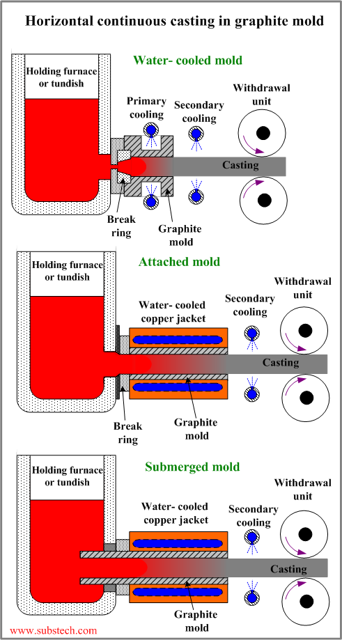
 Different configurations of graphite molds are presented in the figure.
Directly water-cooled graphite mold. In this mold its surface is sprinkled by water stream. This type of cooling is very effective due to elimination of air gap between the graphite mold surface and the coolers. High cooling rates achieved in the directly water-cooled mold allow to use short molds and reach relatively high withdrawal speeds. Fast formation of thick and strong casting “skin” permit in many cases to pull the casting from the mold in non-intermittent regime without pauses and reverse steps. The resulted micro-structure is fine and homogeneous. The disadvantages of the method are: too thick defective surface layer, which should be machined; high thermal stresses caused by high cooling rate; inconvenient (open) water circulation system.
Graphite mold cooled by water-cooled copper blocks. Cooling rate in this method is relatively low due to the air gap between the graphite mold surface and the surfaces of the copper coolers. Molds of this type are longer than directly water-cooled graphite molds. Thin and weak casting “skin” formed in the mold may tear due the friction with the graphite surface therefore casings solidified in molds with water-cooled copper coolers are pulled by an intermittent regime (with pauses and reverse steps). Low cooling rate and intermittent pulling result in less homogeneous micro-structure.
Graphite mold attached to the holding furnace/tundish. In this case the mold is connected to the holding vessel through a break ring - ceramic part providing steady supply (feeding) of liquid metal to the mold. The break ring should conform the mold cross-section. Mold connection is relatively simple. The disadvantage of the mold structure is possible retreat of the solidification front out of the mold space (solidification of the metal in the break ring) during emergency pauses of the withdrawal process. This makes impossible restarting the casting withdrawing.
Submerged graphite mold. The enter tip of the graphite mold is prominent into the holding vessel space and submerged into the melt. Such configuration allows to stop the withdrawal process for any time and then restart it. Solidification front stays within the mold.
One of the applications of the methods of casting in graphite mold is Continuous casting of aluminum based bearing alloys (water cooled mold and submerged mold).
to top
Withdrawal regime of horizontal continuous casting
Stable extraction of continuous casting without tears and cracks is dependent on the following factors:
- Primary cooling rate. High cooling rates favor formation of thick and strong “skin”, which does not tear as a result of friction.
- Graphite quality. Graphite possessing low porosity and high thermal conductivity provide low friction and high cooling rate.
- Temperature interval of solidification (difference between the liquidus and solidus temperatures) of the cast alloy. The alloys with wide temperature interval of solidification may form tears in the mushy zone (partially solidified alloy) during the casting withdrawal.
- Presence of constituents wetting the graphite and penetrating into the graphite pores (Ni, Zn, Sn). Extraction of the castings containing such constituents is characterized by increased friction and sticking to the graphite surface, which may result in cracks and tears.
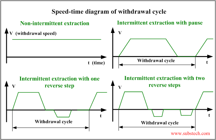
Combination of the above factors determines the withdrawal regime:
(the regimes are also presented graphically in the figure below)
- Non-intermittent extraction. This regime is generally used for casting alloys with low temperature interval of solidification (eg. pure metals) and in casting at high cooling rate (Horizontal continuous casting in graphite mold#Configurations of continuous casting graphite molds|directly water-cooled graphite mold).
- Intermittent extraction with a pause. This regime is used for casting at lower cooling rates. The withdrawal cycle consists of a forward stroke followed by a pause. During the pause the portion of the melt entered the mold starts solidification forming strong skin, which will not tear in the next extraction cycle.
- Intermittent extraction with one reverse step. The alloys having wide temperature interval of solidification are withdrawn by this regime. The skin formed during the pause is not strong enough therefore it tears during subsequent cycle. The reverse step followed by the forward stroke causes closing and healing the tears (cracks).
- Intermittent extraction with two reverse steps. This regime is used for casting alloys containing constituents penetrating into the graphite pores and causing sticking the casting to the graphite surface. The second reverse step following after the solidification pause results in disconnecting the stuck casting from the graphite. The second reverse step is immediately followed by the next forward stroke.
Useful rules and tips for casting engineers
- It is very important that the adjacent surfaces of the copper cooler and the mold are flat and smooth (max. roughness 0.002”/0.05 mm).
- The coolers should be filled with water during the furnace/tundish preheating in order to prevent distortion.
- During preheating the mold tip should be protected from oxidation by ceramic cloth (or similar).
- It is necessary to inspect visually the mold, to check a presence of defects and cracks particularly in the part prominent from the cooler.
- Deviation of the mold from horizontal direction should not be more than 0.02%.
- The less the cross-section (thickness in case of strip casting) of the cast bar – the higher should be the liquid metal temperature in the holding vessel.
- It is recommended to start casting at lower melt temperature and then it may be gradually increased.
- It is recommended to start at low temperature of the outgoing cast bar and lower withdrawal speed and then the temperature and the speed may be gradually increased.
- If cracks or tears form, the temperature of the outgoing cast bar and the casting speed should be decreased and then after disappearing the cracks the temperature and the speed may be increased again.
- If cracks or tears form the temperature in the holding furnace/tundish should be increased and then after disappearing the cracks the temperature may be decreased again.
- Large extraction steps permit to increase the average speed however the resulted structure is non-homogeneous.
- Small extraction steps result in more homogeneous structure but lower productivity.
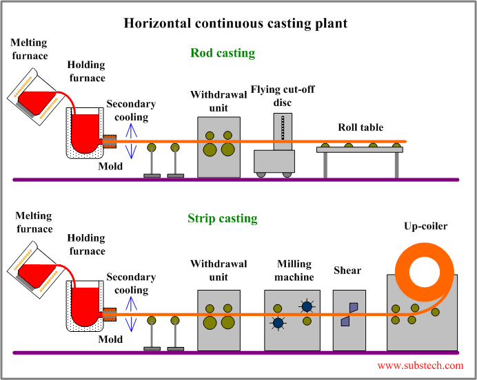
Horizontal continuous casting plant
The typical configurations of horizontal continuous casting plant are presented in the figure:

to top
Related internal links
to Metals
to Foundry technologies
