Main page
About us
Sliding Bearings Consulting
Advertising Opportunities

SubsTech’s sister website Smooth Sliding provides independent engineering consulting services that help you to solve engine bearing related issues: failures, material selection, geometry design and optimization of hydrodynamic conditions.
Smooth Sliding is an engineering consulting company run by Dr. Dmitri Kopeliovich:

- VP R&D of King Engine Bearings.
- World leading expert (32 years of experience) in design, technology and materials for Engine bearings in applications such as automotive, renewable energy, aviation, racing and others.
- Founder and owner of SubsTech (Substances & Technologies) – a leading professional website on Materials Science and Engineering.
- Author of numerous scientific and engineering publications and patents.
- Founder and owner of Smooth Sliding.
For further information and for requesting consulting services please visit our sister website Smooth Sliding.
to Metals
to Engine bearings
Geometry of Engine Bearings
Hydrodynamic lubrication
Engine bearings operate mostly in the hydrodynamic regime of lubrication, in which the bearing surface is separated from the journal surface by the pressurized lubricant film generated by the journal rotation (hydrodynamic bearing).
Normally the rotating journal is displaced from the concentric position and forms a converging gap between the bearing and journal surfaces. The pumping action of the journal forces the oil to squeeze through the wedge shaped gap generating a pressure. The oil pressure creates a supporting force separating the journal from the bearing surface.
The minimum value of the oil film thickness may reach down to 0.5 µm/0.00002” (1/100 of a human hair diameter). Such a minor gap between the bearing and the journal surfaces explains the importance of keeping the dimensions, shapes and the surface quality of the parts at very tight tolerances.
An engine bearing assembly includes three parts: the bearing housing (either big end of the connecting rod or the crankcase main bearing housing), the engine bearing itself (the shells) and the journal (the crank pin or the main journal). Dimensions and tolerances of each of them affect the bearing operation.
Bearing Wall Thickness and Oil Clearance
The basic geometrical parameter of an engine bearing is the oil clearance - the difference between the inside diameter of the bearing installed in the housing and the diameter of the journal (the inside bearing diameter is measured at 90° to the parting line). Oil clearance should have an optimal value providing the desirable combination of the lubrication parameters.
Higher oil clearance causes an increase of the oil flow passing through the bearing and resulting in a lower oil temperature rise. However higher clearance produces less uniform distribution of the oil pressure - greater pick pressure, which increases the probability of the bearing material fatigue. Minimum oil film thickness decreases at higher pressure and may cause direct metal-to-metal contact between the mating surfaces. Too high clearance produces excessive vibration and noise. Lower oil clearance results in a more uniform oil film pressure distribution and a greater oil film thickness however too small clearance causes overheating the oil and a sharp drop of its viscosity.
High performance bearings has an increased clearance providing more stable hydrodynamic lubrication under conditions of high loads and high rotation speeds.
The effect of the rotation speed and load on the hydrodynamic lubrication of a connecting rod engine bearing is depicted in Fig.1 and 2. The input parameters of the bearing and lubrication conditions are in Table 1.
Table 1 Input Parameters
| Bearing diameter, mm | 47.0 mm | 1.8504 ” |
| Bearing length | 15.0 mm | 0.5906” |
| Rotation speed | 2000-4000 RRM | 2000-4000 RRM |
| Force | 30-70 kN | 6744 – 15737 lbs. |
| Specific load | 42.6 – 99.3 MPa | 6179 – 14402 psi |
| Oil inlet temperature | 80 °C | 176 °F |
| Feed pressure | 2.5 bar | 36.3 psi |
| Absolute clearance | 10-108 µm | 0.4 – 4.3 thou |
| Wall thickness eccentricity | 0-20 µm | 0-0.8 thou |
The maximum value of the minimum oil film thickness (MOFT) characterizes stability of the hydrodynamic regime of lubrication. The greater the MOFT, the more stable the regime of hydrodynamic lubrication established in the bearing. The optimal oil clearance at the load 30 kN for the rotation speed 2000-4000 RPM (Fig.1) is approx. 65 µm (2.6 thou).
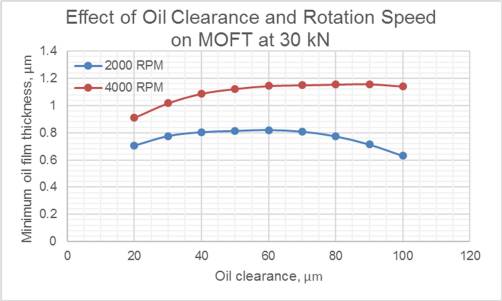
Fig.1
At higher load 70 kN the optimal oil clearance decreases (Fig.3) to approx. 50 µm (0.2 thou).
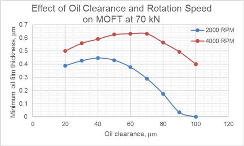
Fig.2
Bearing thickness directly influences the value of oil clearance. Oil clearance determines the hydrodynamic parameters of lubrication, including oil temperature rise, oil pressure distribution, oil flow, minimum oil film thickness, energy loss and coefficient of hydrodynamic friction. If the values of bearing thickness are scattered within a wide range, the hydrodynamic parameters will vary accordingly. Consistency of wall thickness produces more consistent hydrodynamic characteristics and a more stable regime of hydrodynamic lubrication.
The wall thickness tolerance accepted in the industry of engine bearings is between ± 4 µm (0.16 thou) to ± 6 µm (0.24 thou). This means that the oil clearance tolerance of bearings may vary within 16 (±8) - 24 (±12) µm (0.63-0.94 thou).
Fig.3 and 4 depict the effect of oil clearance tolerance and load at 2000 RPM and 4000 RPM on the MOFT. The values of MOFT are calculated at values of oil clearance varying with the increment 24 µm (0.94 thou).
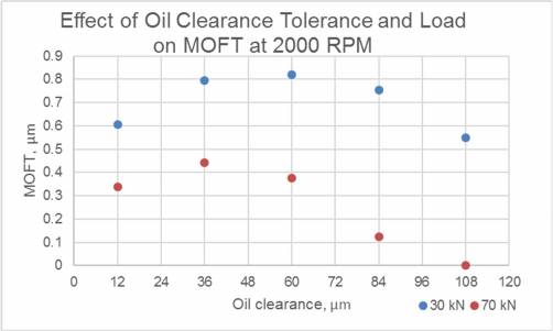
Fig.3
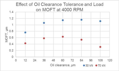
Fig.4
The variation of MOFT within 24 µm (0.94 thou) oil clearance tolerance are acceptable (insignificant) if the oil clearance value is close to the optimal.
to top
Eccentricity of Engine Bearings
Rotation of the crankshaft produces inertia forces generated by the accelerating/decelerating engine parts (e.g. the assembly of a piston with the connecting rod).
The values of inertia forces are proportional to the square of the rotation speed, they become high at high rotation speeds. For example, an increase of rotation speed from 2000 to 6400 RPM raises the inertia forces by 10 times.
In reaction to these inertia forces, the connecting rod and its bore are stretched and contracted in a vertical direction (Fig.5).
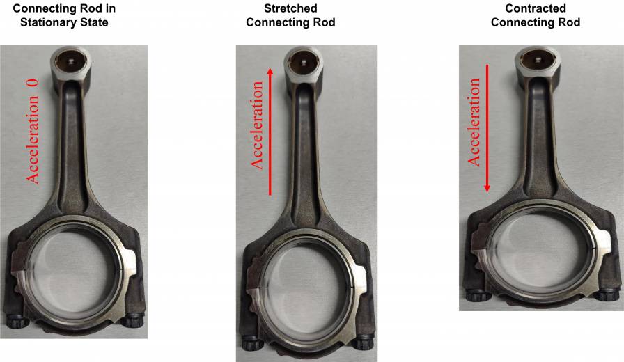
Fig.5 Distortion of Connecting Rod under Inertia Forces
The circular big end bore at the stationary conditions becomes ellipsoidal when the rod is stretched by the inertia forces (Fig.6). The bore diameter in the longwise direction increases whereas the bore diameter in the transverse direction decreases:
Dv > D0
Dh < D0
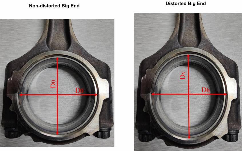
Fig.6 Distortion of Big End
As a result, bearing diameter measured along the parting line closes-in, changing the shape of the oil wedge. The oil wedge may change its shape from converging to diverging (negative oil wedge). Such conditions are shown in Fig.7.
Under negative oil wedge conditions, a hydrodynamic regime of lubrication is impossible. The bearing will be subject to direct friction, characterized by metal-to-metal contact between it and the crankshaft journal surface.
The crankcase bores may also change their shape as a result of high loads applied to the main bearings. Therefore a similar problem may occur with them.
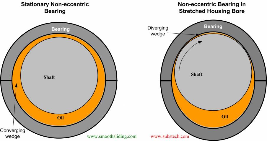
Fig.7 Non-eccentric Bearing
In order to prevent breaking hydrodynamic friction, the inside bearing surface is produced not round. It has a lemon shape (fig.8) due to the varying thickness of the bearing wall, having its maximal value at the centerline (s3) and gradually decreasing towards the parting line. It is accepted to measure the minimal value of bearing wall thickness (s3-u) at a certain specified height a1 or at a specified angle α2 (Fig.8 and 9), in order to exclude the zone of crush relief. u - wall thickness reduction at angle α2. It is common to measure u at α2=25⁰.
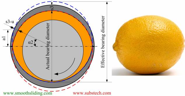
Fig.8 Bearing Eccentricity (Lemon Shape)
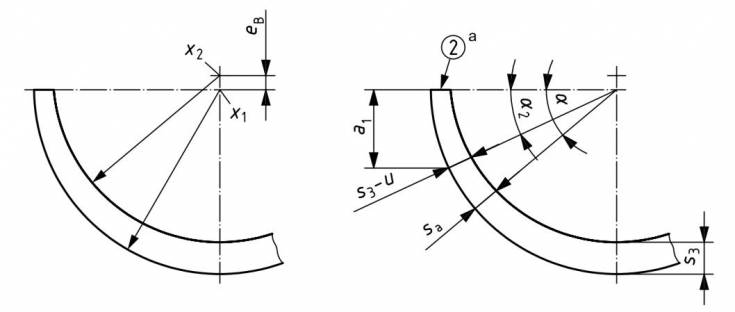
Fig.9 Measurement of Eccentricity (ISO 3548)
Fig.10 depicts that the eccentric (lemon shaped) bearing retains converging wedge under the conditions of distorted (stretched) housing bore.
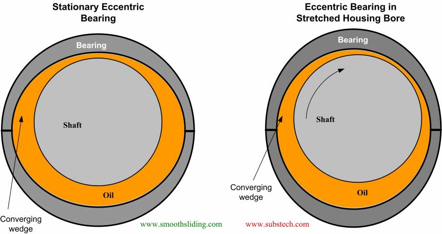
Fig.10 Eccentric Bearing
Distortion (stretching) of the housing bore causes a decrease of the actual (effective) oil clearance and the oil converging wedge in the zone of maximum oil film pressure. The eccentric profile of the bearing wall increases the oil wedge.
The effect of eccentricity u on the minimum oil film thickness at 40 and 70 kN (8992 and 15737 lbs.) at the rotation speed 4000 RPM is depicted in Fig.11 and 12.
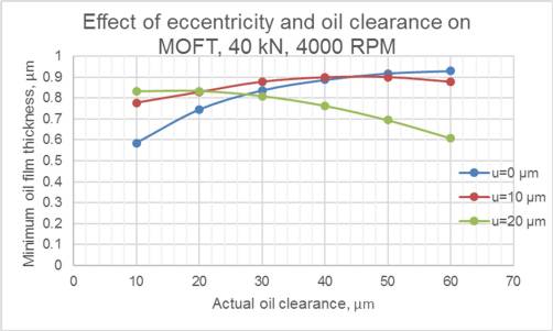
Fig.11
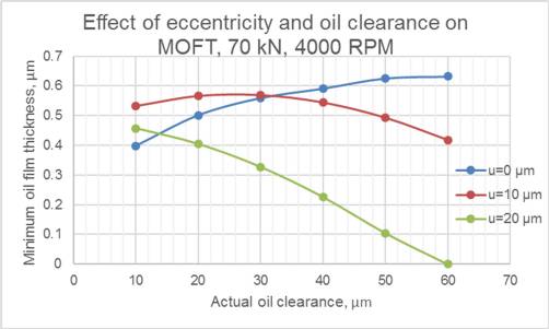
Fig.12
Eccentric (lemon shaped) bearing performs better (generates greater values of MOFT) under the conditions of the effective oil clearance decreased to 10-20 µm (0.4-0.8 thou).
to top
Crush Relief
In addition to the gradual thickness reduction (eccentricity) the bearing wall is machined at the parting lines to make zones of crush relieves (Fig.13).
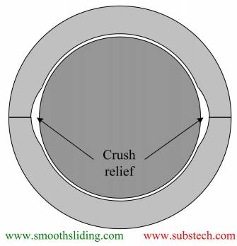
Fig.13 Crush Relief
Crush relief prevents disturbance of hydrodynamic lubrication which may occur at the parting line due to the imperfections of the bearing geometry in the split zone.
Two bearing shells may not mate to each other because of an imperfect adjacent to the housing surface or a slight difference in the wall thickness at the joint (Fig.14).
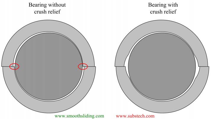
Fig.14 Effect of Crush Relief (Imperfect Joint)
Another imperfection of the bearing profile geometry at the joint zones may occur in form of inward protrusion of the bearing material caused by its deformation under press fit stresses (Fig.15).
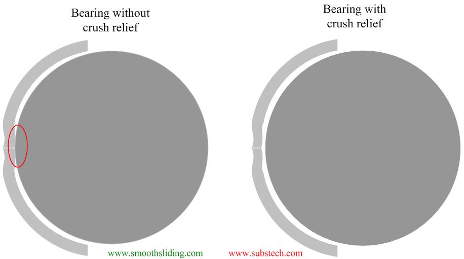
Fig.15 Effect of Crush Relief (Inward Deformation)
The length (a6) and depth (i1) of the crush relief affect oil leakage out of the bearing. Excessive crush relief facilitates oil leakage out of the bearing and may cause oil starvation and breaking the hydrodynamic regime of lubrication.
Therefore the dimensions and tolerances of crush relief determined in the bearing design (Fig.16) are controlled in the manufacturing process.
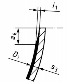
Fig.16 Crush Relief Dimensions (ISO 3548)
to top
Summary
The following parameters of engine bearing geometry and their role in the bearing operation are considered:
- The effect of oil clearance, rotation speed and load on the stability of hydrodynamic lubrication and value of minimum oil film thickness of engine bearings.
- The effect of the engine bearing wall thickness within the acceptable tolerances on the consistency of hydrodynamic lubrication.
- How eccentricity of the engine bearing profile (lemon shape) helps to maintain required oil wedge and prevent breaking the regime of #HydrodynamicLubrication of a bearing in the distorted housing.
- The effect of the eccentricity value and effective oil clearance on the minimum oil film thickness of the engine bearings at various loads.
- The possible imperfections of the #EngineBearing geometry at the parting line and purpose of the crush relief.
Related internal links
to Metals
to Engine bearings


