SubsTech’s sister website Smooth Sliding provides independent engineering consulting services that help you to solve engine bearing related issues: failures, material selection, geometry design and optimization of hydrodynamic conditions.
Smooth Sliding is an engineering consulting company run by Dr. Dmitri Kopeliovich:
- VP R&D of King Engine Bearings.
- World leading expert (32 years of experience) in design, technology and materials for Engine bearings in applications such as automotive, renewable energy, aviation, racing and others.
- Founder and owner of SubsTech (Substances & Technologies) – a leading professional website on Materials Science and Engineering.
- Author of numerous scientific and engineering publications and patents.
- Founder and owner of Smooth Sliding.
For further information and for requesting consulting services please visit our sister website Smooth Sliding.
to Metals
to Engine bearings
Geometrical parameters of engine bearings
Hydrodynamic lubrication

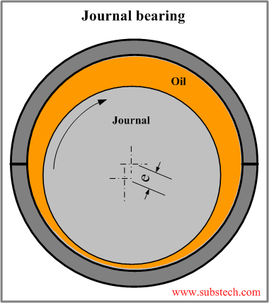
Engine bearings operate mostly in the hydrodynamic regime of lubrication (Hydrodynamic journal bearing), in which the bearing surface is separated from the journal surface by the pressurized lubricant film generated by the journal rotation.
Normally the rotating journal is displaced from the concentric position and forms a converging gap between the bearing and journal surfaces. The pumping action of the journal forces the oil to squeeze through the wedge shaped gap generating a pressure. The oil pressure creates a supporting force separating the journal from the bearing surface.
The minimum value of the oil film thickness may reach down to 0.00002” (1/100 of a human hair diameter). Such a minor gap between the bearing and the journal surfaces explains the importance of keeping the dimensions, shapes and the surface quality of the parts at very tight tolerances.
An engine bearing assembly includes three parts: the bearing housing (either big end of the connecting rod or the crankcase main bearing housing), the engine bearing itself (the shells) and the journal (the crank pin or the main journal). Dimensions and tolerances of each of them affect the bearing operation.
to top
Oil clearance
The basic geometrical parameter of an engine bearing is the oil clearance - the difference between the inside diameter of the bearing installed in the housing and the diameter of the journal (the inside bearing diameter is measured at 90° to the parting line).
Oil clearance should have an optimal value providing the desirable combination of the lubrication parameters.
Higher oil clearance causes an increase of the oil flow passing through the bearing and resulting in a lower oil temperature rise. However higher clearance produces less uniform distribution of the oil pressure - greater pick pressure, which increases the probability of the bearing material fatigue. Minimum oil film thickness decreases at higher pressure and may cause direct metal-to-metal contact between the mating surfaces. Too high clearance produces excessive vibration and noise. Lower oil clearance results in a more uniform oil film pressure distribution and a greater oil film thickness however too small clearance causes overheating the oil and a sharp drop of its viscosity. High performance bearings has an increased clearance providing more stable hydrodynamic lubrication under conditions of high loads and high rotation speeds.
Typical values of oil clearance C :
Passenger cars:
Cmin = 0.0005*D Cmax = 0.001*D
High performance cars:
Cmin = 0.00075*D Cmax = 0.0015*D
where D - the journal diameter.
to top
Eccentricity
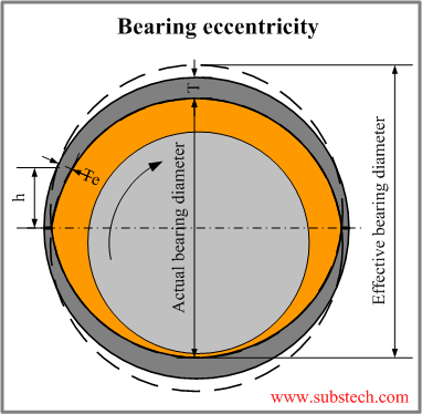
The inside bearing surface is not round. It has a lemon shape due to the varying thickness of the bearing wall having maximal value at the centerline (T) and gradually decreasing towards the parting line. It is accepted to measure the minimal value of the bearing wall thickness (Te) at a certain specified height h in order to exclude the zone of the crush relief.

The difference between the maximal and minimal wall thickness is called eccentricity:
eccentricity = T - Te
Eccentricity produced by the varying wall thickness is added to the eccentricity “e” caused by the displacement of the journal from the concentric position. Such increased total eccentricity allows to establish a more stable regime of hydrodynamic lubrication.
With regards to the hydrodynamic conditions the bearing with an eccentricity is equivalent to the bearing with an increased diameter (or increased oil clearance). The oil wedge of the bearing with eccentricity is the same as the wedge formed by the bearing with an increased diameter (”effective bearing diameter”). On the other hand the actual bearing diameter is not changed, thus the adverse effect of the bearing clearance on the vibration and noise is prevented.
Bearing eccentricity is designed to compensate distortions of the bearing housing bores caused by the forced applied to the connecting rod and to the crankcase. Under the forces the housing bore is stretched in the vertical direction. As a result the bearing diameter measured along the parting line decreases (close-in) changing the shape of the oil wedge. The bearing eccentricity allows to retain the wedge shape of the oil gap, which is required for hydrodynamic regime of lubrication. High performance engine bearings operating at high rotation speed and high loads have an increased amount of eccentricity.
Advanced quality control of machining operations allows to produce bearings with tight tolerance. Such tight tolerances result in superior consistency of the oil clearance and eccentricity.
Recommended values of eccentricity:
For passenger cars: 0.0002 - 0.0008” For high performance cars: 0.0006 - 0.0012”
Location of the eccentric wall measurement (h) is within the range 1/4-5/8” depending on the journal diameter. h=3/8” for 1.6-3.4” journals.
to top
Crush height
The outside diameter of an engine bearing is always greater than the diameter of its housing. The difference between the diameters affects the amount of the elastic compression of the bearing installed in the housing. Firmly tightened bearing has a uniform contact with the housing surface, which prevents the bearing displacement in the housing during the operation, provides maximum heat transfer through the contacting surfaces and increases the rigidity of the housing. Since the direct measurement of the bearing circumference is a difficult task, another parameters characterizing the bearing press fit is commonly measured - crush height.
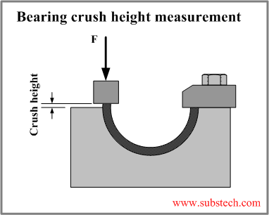
Crush height is the difference between the outside circumferential length of a half bearing (one half shell) and the half of the housing circumference. The figure presents a scheme of the device for measuring crush height.

The tested bearing is installed in the gauge block and pressed with a predetermined force F. The force is proportional to the cross-section area of the bearing wall.
The value of the crash height is dependent on the bearing diameter, housing material (modulus of elasticity and thermal extension), housing stricture (rigidity) and the temperature.
High performance engine bearings working at high loads and increased temperatures are designed with an increased crush height, which provides better heat transfer and a greater press fit in the bearing housing.
Typical values of the crush height of 1.5-2.5” diameter bearings:
For passenger cars: 0.001-0.002” For high performance cars: 0.002-0.004”.
to top
Crankshaft
Significant part of engine bearing damages is caused by defects of the journals. The basic geometrical parameter of a journal is its diameter. The required relationship between the housing bore diameter, the bearing wall thickness and the journal diameter determines the value of the oil clearance within the tolerances providing a reliable hydrodynamic lubrication.
Commonly crankshafts have a diameter tolerance 0.0005-0.001”.
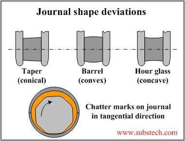
Ideally a journal has a cylindrical shape. However the actual journal shape may deviate from the perfect cylinder. If the journal pin diameter varies in the axial direction the journal shape forms one of the following patterns: taper (conical), barrel (convex) or hour glass (concave). The taper/barrel/hour glass journal diameter deviation should be not greater than: 1/10,000 of the journal length (for tri-metal bearings), 2/10,000 of the journal length (for bi-metal bearings). Variations of the journal diameter in the tangential direction produce roundness defects: ovality or waves along the circumference of the journal (grinding chatter marks). Chatter marks produce undesirable shape of the oil gap breaking the oil film between the bearing and journal surfaces. Out-of-round deviations of a journal should be maximum 0.00004”.

The main pins of a crankshaft should be aligned (concentric). Misalignments (deviations from concentricity) may cause direct contact between the bearing and the misaligned journal pin. Misalignments are particularly dangerous for tri-metal bearings having a thin overlay, which may be removed by the contacting journal.
Recommendations for maximum misalignment of the main pins:
For tri-metal bearings: 0.001” overall value; 0.0005” on adjacent journals.
For bi-metal bearings: 0.002” overall value; 0.001” on adjacent journals.
The pins of a crankshaft should be parallel to each other. Maximum deviations from the parallelism: 0.0005” for tri-metal bearings and 0.001” for bi-metal bearings.
Excessive wear of a bearing surface may also be caused by a direct metal-to-metal contact due to the journal surface roughness. Surface quality is particularly important in the bearings operating with low oil film thickness (highly loaded bearings, low viscosity oils). Reliable hydrodynamic lubrication is guaranteed if two surface quality characteristics are controlled: Ra (average roughness) and Rz (average maximum height of the profile):
For low and medium loaded bearings: Ra = 15 microinch max. Rz = 60 microinch max.
For highly loaded bearings: Ra = 10 microinch max. Rz = 30 microinch max.
to top
Crankcase
Bores have a diameter tolerance 0.001”.
Surface finish of bores: 60-90 microinch.
Out-of-round (ovality) is allowed only if the diameter in the horizontal direction (along the parting line) is larger than that in the vertical direction. Otherwise the bearing eccentricity required for establishing stable hydrodynamic lubrication may be too low. The maximum out-of-round is 0.001”.
Recommendations for maximum misalignment of the bores:
For tri-metal bearings: 0.001” overall value; 0.0005” on adjacent bores.
For bi-metal bearings: 0.002” overall value; 0.001” on adjacent bores.
to top
Connecting rod
Bores have a diameter tolerance 0.0005”.
Surface finish of bores: 60-90 microinch.
Out-of-round (ovality) is allowed only if the diameter in the horizontal direction (along the parting line) is larger than that in the vertical direction. The maximum out-of-round is 0.001”.
The taper/barrel/hour glass journal diameter deviation should be not greater than: 1/10,000 of the bearing length (for tri-metal bearings), 2/10,000 of the bearing length (for bi-metal bearings).
Parallelism between rod bore and wrist pin hole: 0.001” max.
Twist: 0.001” max.
to top
Related internal links
to Metals
to Engine bearings