Main page
About us
Sliding Bearings Consulting
Advertising Opportunities

SubsTech’s sister website Smooth Sliding provides independent engineering consulting services that help you to solve engine bearing related issues: failures, material selection, geometry design and optimization of hydrodynamic conditions.
Smooth Sliding is an engineering consulting company run by Dr. Dmitri Kopeliovich:
- VP R&D of King Engine Bearings.
- World leading expert (32 years of experience) in design, technology and materials for Engine bearings in applications such as automotive, renewable energy, aviation, racing and others.
- Founder and owner of SubsTech (Substances & Technologies) – a leading professional website on Materials Science and Engineering.
- Author of numerous scientific and engineering publications and patents.
- Founder and owner of Smooth Sliding.
For further information and for requesting consulting services please visit our sister website Smooth Sliding.
to Metals
to Engine bearings
Hydrodynamic journal bearing
Dr. Dmitri Kopeliovich
Hydrodynamic journal bearing is a bearing operating with hydrodynamic lubrication, in which the bearing surface is separated from the journal surface by the lubricant film generated by the journal rotation.
Most of engine bearings are hydrodynamic journal bearings.
Journal bearing operation

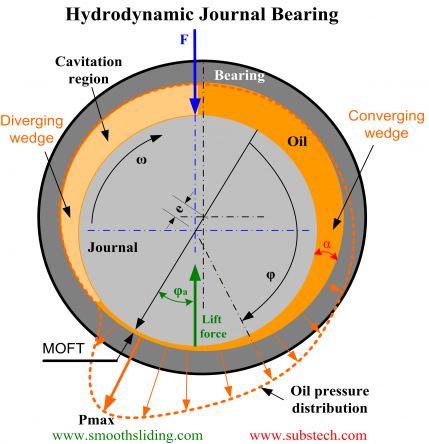
The figure demonstrates a hydrodynamic journal bearing and a journal rotating in a clockwise direction.
Journal rotation causes pumping of the lubricant (oil) flowing around the bearing in the rotation direction.
If there is no force applied to the journal its position will remain concentric to the bearing position. However a loaded journal displaces from the concentric position and forms a converging gap between the bearing and journal surfaces.
The pumping action of the journal forces the oil to squeeze through the wedge shaped gap generating a pressure.
The pressure falls to the cavitation pressure (close to the atmospheric pressure) in the diverging gap zone where cavitation forms.
According to Michael M. Khonsari and E. Richard Booser two types of cavitation may form in journal bearing:
- Gaseous cavitation associated with air and other gases dissolved in oil. If the oil pressure falls below the atmospheric pressure the gases tend to come out of the oil forming gaseous cavitation voids. The cavities are carried by the circulating oil to the pressurized converging gap where they redissolve in the oil and disappear without any damaging effect.
- Vapor cavitation forms when the load applied to the bearing fluctuates at high frequency (e.g. bearings in high RPM internal combustion engines). The oil pressure instantly falls causing formation of cavities due to fast evaporation (boiling). When the pressure rises the vapor cavities (cavitation bubbles) contract at high velocity. Such collapse results in impact pressure, which may erode the bearing material.
The oil pressure creates a supporting force separating the journal from the bearing surface.
The force of oil pressure and the hydrodynamic friction force counterbalance the external load F.
The final position of the journal is determined by the equilibrium between the three forces.
In the hydrodynamic regime the journal “climbs” in the rotation direction (left side of the bearing).
If the journal works in boundary and mixed lubrication the hydrodynamic pressure force disappears (the other two forces remain). Thus, the “climbing” direction is opposite to the rotation direction and the journal rolls up the right side of the bearing.
to top
Reynolds Equation
Lubricant pressure distribution as a function of journal speed, bearing geometry, oil clearance and lubricant viscosity is described by Reynolds equation:

Where:
h – local oil film thickness,
η – dynamic viscosity of oil,
p – local oil film pressure,
U – linear velocity of journal,
x - circumferential direction.
z - longitudinal direction.
Close form solution of Reynolds equation can not be obtained therefore finite elements method is used to solve it.
Analytical solutions of Reynolds equation exist only for certain assumptions:
- Sommerfeld Solution
The equation is solved with the assumption that there is no lubricant flow in the axial direction (infinitely long bearing assumption).

- Ocvirk Solution
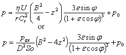
Ocvirk solution for infinitely short bearing assumption neglects circumferential pressure gradients (first term of Reynolds equation).

Where:
Cr – radial clearance Cr = (D-Dj)/2,
r – bearing radius,
Dj - journal diameter,
ε - eccentricity ratio ε = e/Cr
e - absolute bearing eccentricity,
B – bearing length,
p0 - cavitation pressure,
So - Sommerfeld number (see below).
Sommerfeld and Ocvirk solutions are applicable only in the region of positive pressure.
to top
Engineering calculations of journal bearing performance
Engineering analysis of a journal bearing performance may be made by using Raimondi-Boyd charts containing numerical solutions of Reynolds equation for bearings with different length-to-diameter ratio.
These engineering calculations are based on the dimensionless bearing parameter called Sommerfeld number:
So = F Ψ²/(DBωη)
Where:
F – bearing load,
Ψ – relative bearing clearance Ψ = (D-Dj)/D,
B – bearing length,
D – bearing diameter,
Dj - journal diameter,
η – dynamic viscosity of oil,
ω – angular speed of journal.
Raimondi-Boyd analysis is based on the assumption that the oil viscosity does not change when it passes through the bearing. Since the real oil heats up in the bearing and its viscosity drops it is assumed that oil viscosity is determined at the effective temperature Teff = Ten + 0.5ΔTas (ΔTas is assumed temperature rise).
The calculation procedure is as follows:
- Temperature rise ΔTas is assumed.
- Effective temperature Teff = Ten + 0.5ΔTas
- Oil viscosity η at the temperature Teff is determined (viscosity-temperature chart).
- Relative bearing clearance is calculated Ψ = (D-Dj)/D
- Sommerfeld number is calculated: So = F Ψ²/(DBωη)
- Values of Sommerfeld number and geometry parameter B/D determine the bearing eccentricity ε, which is obtained from the eccentricity chart ε(So, B/D).
- Minimum oil film thickness hmin = 0.5DΨ(1 – ε)
- Eccentricity value and the geometry ratio B/D are used for determination specific coefficient of friction f’(ε, B/D), angular position of the minimum oil film thickness φ(ε, B/D) and oil flow parameter Q’(ε, B/D).
- Coefficient of friction f = f’Ψ
- Oil flow rate Q = D3ωΨQ’
- Power loss due to friction P = fFωD/2
- Calculated oil temperature rise ΔTca = P/(cQ) where c is specific heat capacity of oil
- Calculated oil temperature rise ΔTca is compared to the assumed value ΔTas and if there is a significant difference between them a new assumption of the temperature rise is made.
The above calculation procedure is repeated for several iterations until the calculated and assumed values of the temperature rise become equal.
to top
Related internal links
to Metals
to Engine bearings


